
1。硬件:
年初从原来的同事那里搞到一块STM32F4Discovery。原来用的CC3D的FC是M3的核,72Mhz, 资源太有限了。现在这个F4主频到168Mhz,ST提供丰富的示例程序,让您更快速的入门STM32F4单片机。
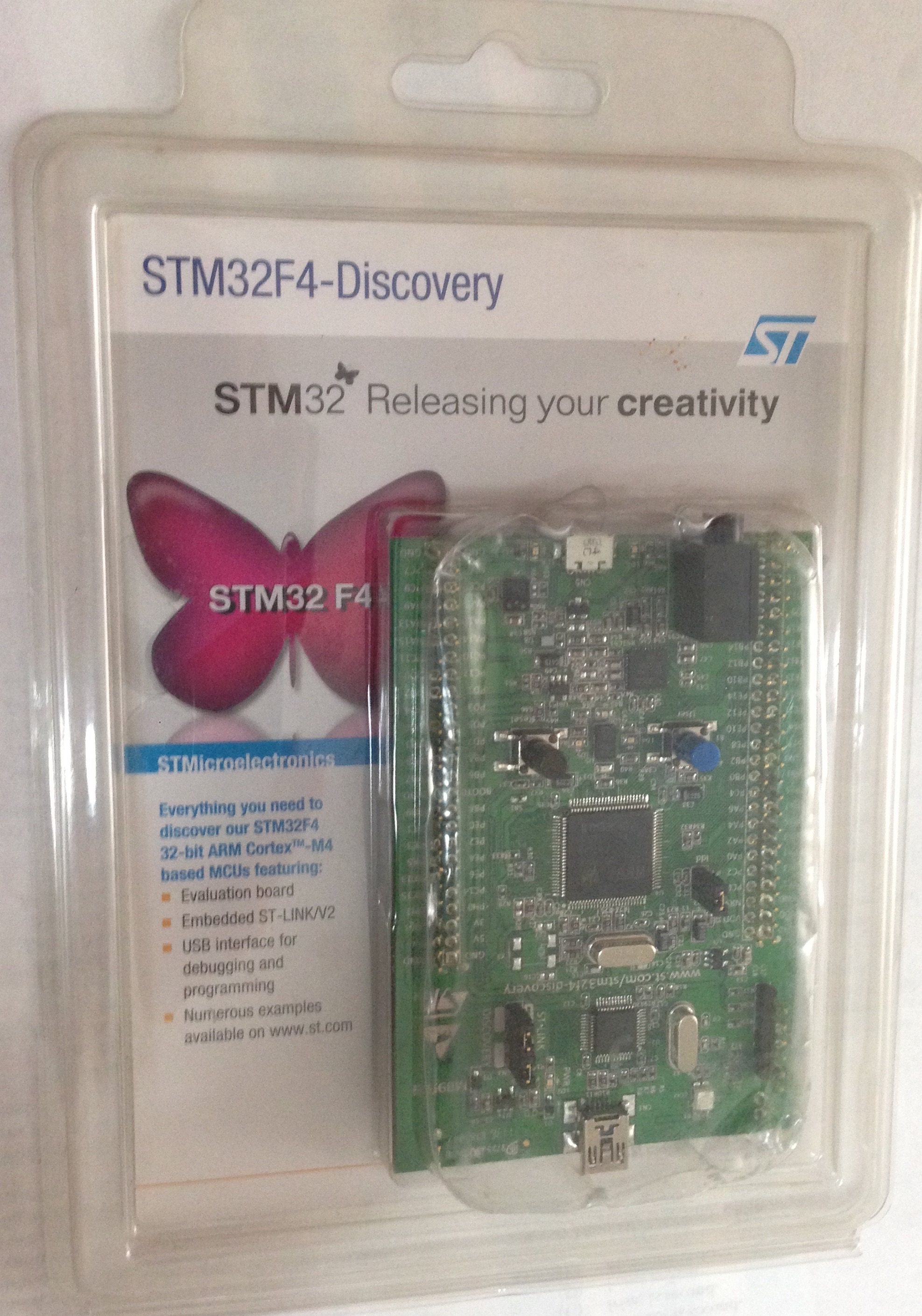
特点
STM32F407VGT6微控制器
1024KB FLASH,192 KB RAM
100引脚,LQFP封装
开发板集成ST-Link/V2的仿真调试器(但仅对外提供SWD接口)
指示灯
LD1:USB通讯指示灯
LD2:3.3V电源指示灯
LD3:应用指示灯
LD4:应用指示灯
LD5:应用指示灯
LD6:应用指示灯
LD7:USB OTG LED(VBus)
LD8:USB OTG LED(over-current)
按键
复位按钮
应用按钮
电源
通过USB取电5V
可对外供电5V和3V
USB OTG FS
micro-AB
传感器
LIS302DL (ST MEMS motion sensor, 3-axis digital output accelerometer)
MP45DT02 (ST MEMS audio sensor, omni-directional digital microphone)
音频驱动
CS43L22 (audio DAC with integrated class D speaker driver)
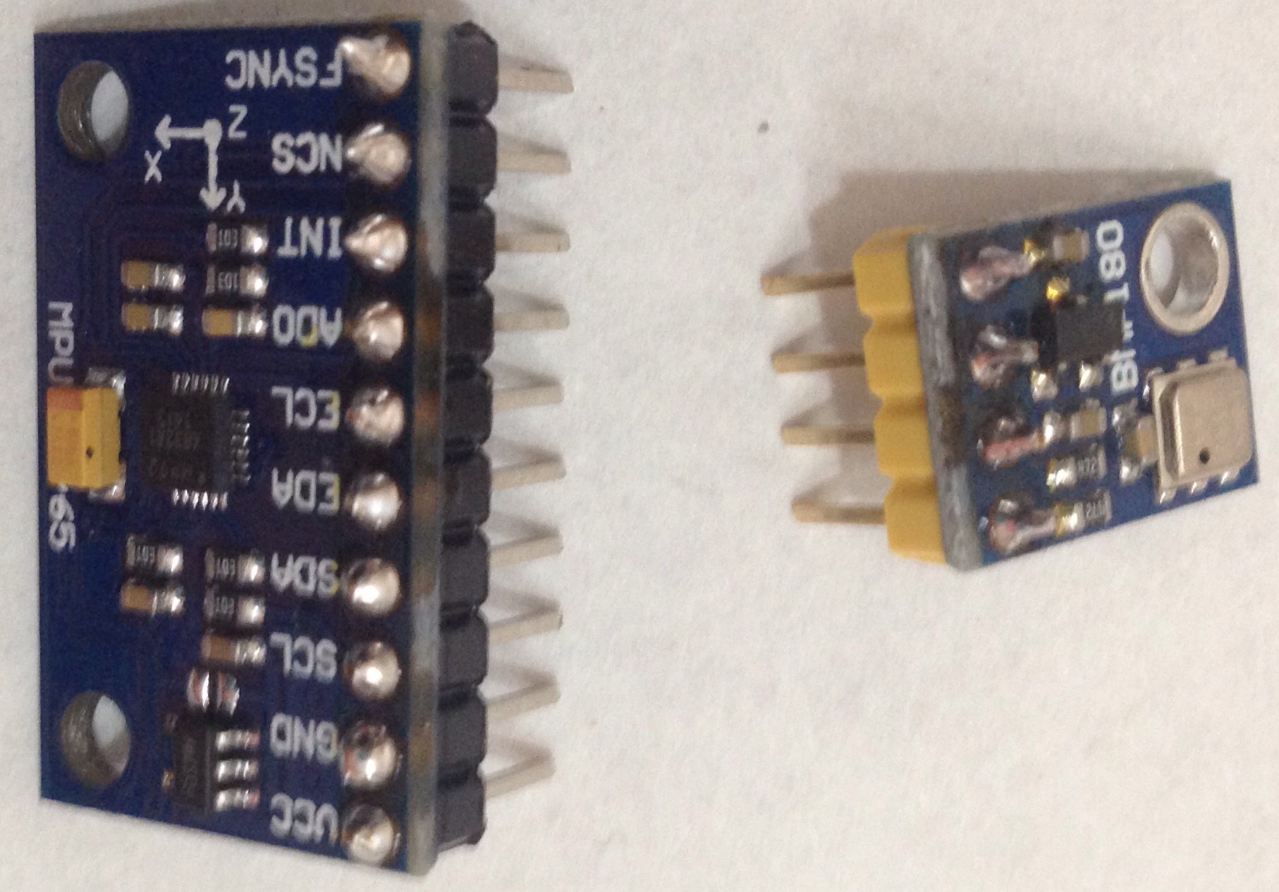
用此开发板做实验真心不错。对于开源的FC软件,现在发现TauLabs(TL:TauLabs.org)的软件支持更多的板子,虽然它也是从Openpilot的一个分支,但看起来发展的更迅猛。考虑到将来集成到体积更小的FC,传感器就要选择集成度更高的9轴传感器:MPU9250,气压传感器可以选择成本更低的BMP180。TB上采购到这两个传感器:
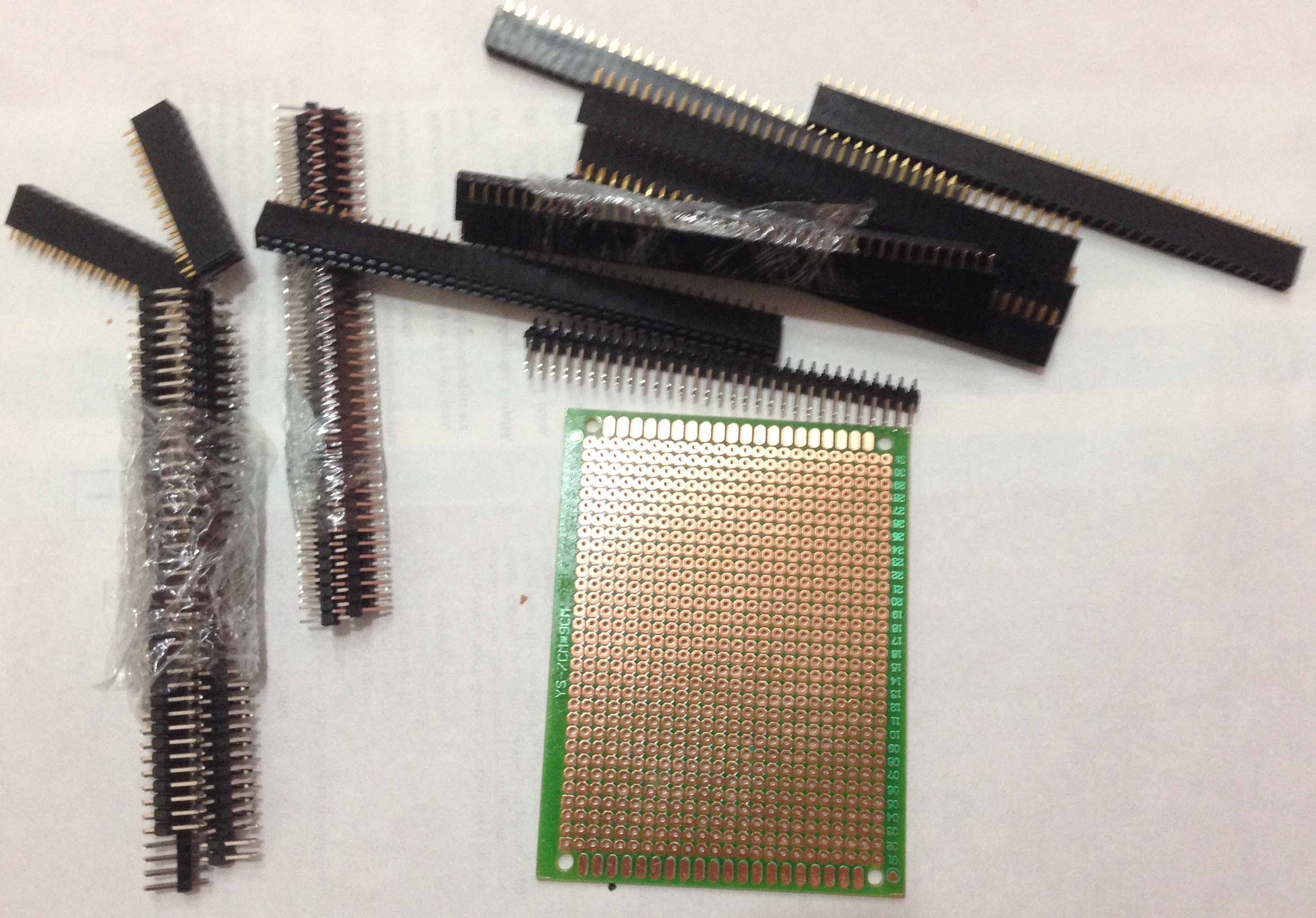
以及PCB和接插件等:
开焊:
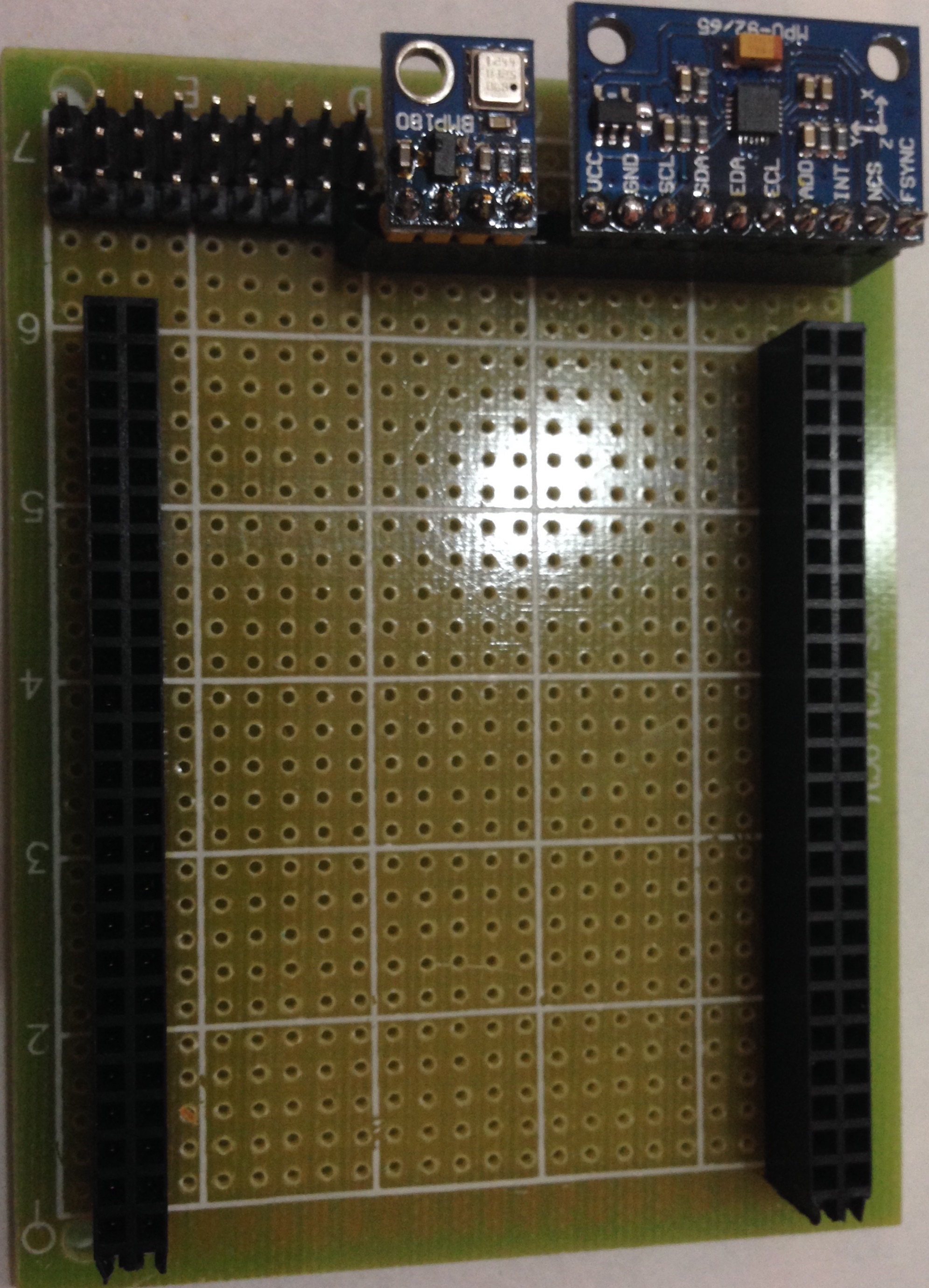
完成:
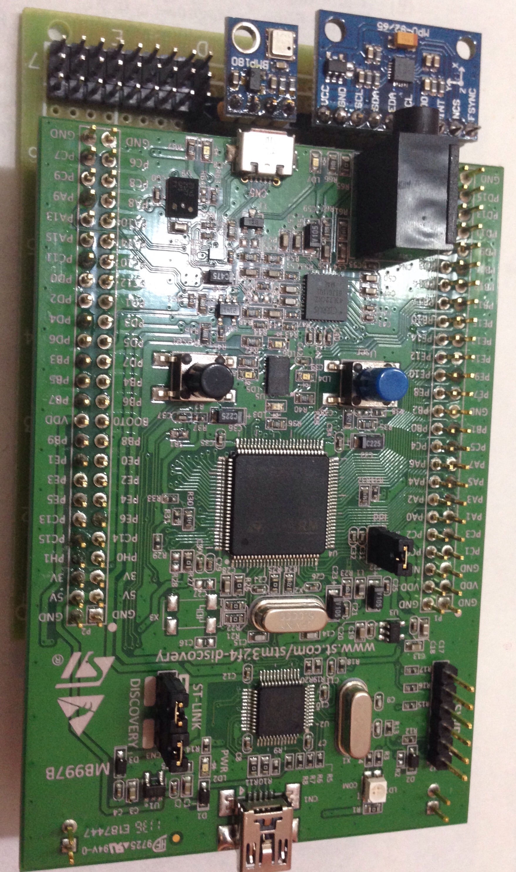
pin脚的使用如下:
PWM inputs:
1: TIM4_CH3 (PB8)
2: TIM2_CH1 (PA0) ;Orignal is PA15, which is for SPI3_NSS now
3: TIM2_CH2 (PA1)
4: TIM8_CH1 (PC6)
5: TIM8_CH3 (PC8)
6: TIM8_CH4 (PC9)
7: TIM9_CH1 (PE5)
8: TIM9_CH2 (PE6)
PWM ouputs:
1: TIM1_CH1 (PE9)
2: TIM1_CH2 (PE11)
3: TIM1_CH3 (PE13)
4: TIM1_CH4 (PE14)
5: TIM3_CH1 (PB4)
6: TIM3_CH2 (PB5)
7: TIM3_CH3 (PB0)
8: TIM3_CH4 (PB1)
MPU9250 INT -> INT_MPU9250(PC0)
MPU9250 CS -> SPI3_NSS(PA15)
MPU9250 SDO -> SPI3_MISO (PC11)
MPU9250 SDI -> SPI3_MOSI(PC12)
MPU9250 SCLK -> SPI3_CLK(PB3)
MPU9250 FSYNC -> GND
BMP180/MS5611 SCL -> I2C1_SCL (PB6)
BMP180/MS5611 SDA -> I2C1_SDA (PB9)
MS5611 CSB -> GND
SPI flash:
FLASH D (15) -> SPI2_MOSI (PB15)
FLASH Q (8) -> SPI2_MISO (PB14)
FLASH C (16) -> SPI2_SCK (PB13)
FLASH /S (7) -> SPI2_NSS (PB12)
FLASH VCC (2) -> 3V
FLASH /HOLD (1) -> 3V
FLASH /W (9) -> 3V
FLASH VSS (10) -> GND
LED
PIOS_LED_GREEN -> PD12
PIOS_LED_ORANGE ->PD13
PIOS_LED_RED -> PD14
PIOS_LED_BLUE -> PD15
UARTs: (VCC configurable by jumper 3V or 5V)
-> 4Pin Header (1)GND,VCC,RXI,TXO
USART1_RXI (PB7)
SBUS_ENABLE (PD9)
USART2_RXI (PA3)
USART2_TXO (PA2)
USART3_RXI (PB11)
USART3_TXO (PD8)
unused
USART4_RXI (PC11)
unused
USART5_RXI (PD2)
2。软件:
a. 首先在Git上免费注册一个账号,然后复制TL as a Branch。 在本地做一个备份用GITHUB进行同步,并建立QT开发环境(为地面站软件开发),GUN C++软件等。
b. 按照TL的文档建立新的目标文档,并针对我选择的传感器进行修改。
Development Adding a new board type
Here are the steps to add a new hardware target. This assumes that the CPU architecture is supported already.
For an overview of the software architecture please read this
Firmware code changes
The changes you will need to make for your target should be largely confined to the flight/targets/<board name> directory,
which you will need to create. It is probably easiest to start by copying a directory of a board most similar to yours.
if you are doing an F1 board, start with flight/targets/coptercontrol
if you are doing an F3 board, start with flight/targets/sparky
if you are doing an F4 board, start with flight/targets/quanton and copy that file to your flight/targets/<board name>
where <board name> is what you want to call your new target.
Main Makefile
flight/targets/<board name>/fw/Makefile
Add your board name (lowercase) to the “ALL_BOARDS” variable Add your board name (capitalised) to the Friendly names variable
If necessary, exclude your board from the boot loader updater targets.
Board-level definitions
Before being able to compile a firmware for this board, you have to configure the build environment so that the PiOS HAL is
mapped to the way the MCU peripherals are configured on your target, how memory is mapped, how the target is programmed, etc.
Update the board-info.mk file
./flight/targets/<board name>/board-info/board-info.mk
This file defines the actual hardware chip used by the board, memory mapping, CPU frequency and programming methods. It also
contains PiOS-related: board model, revision, type.
This contains a lot of the meta information for your target that is packaged into the boot loader and determines details about
the memory layout, as well as the unique board ID. For the board id (BOARD_TYPE) make sure you are not conflicting with the
existing targets.
Board hardware description and power initialization code
flight/targets/<board name>/board-info/board_hw_defs.c
This is one of the most important files for your target, and contains the majority of the hardware mappings. See other examples
for the conventions. It is used by both the main firmware and the bootloader.
flight/targets/<board name>/fw/pios_board.c
This file is the one that predominantly uses board_hw_defs.c to power up the board and contains most of the remainder of the
board specific information.
Add your target to the boards.h file
flight/PiOS/inc/pios_board_info.h
add a board define for your board (for instance STM32F4xx_Revolution.h) update pios_board.h to include this define.
This file is largely historical and more information has been migrating to board_hw_defs.c and pios_board.c, but still contains
various defines for the various peripherals of the MCU are configured for this target (used by the PiOS drivers):
Bootloader Settings
LED defines
SPI
Watchdog
I2C
Serial ports
USB
It also contains application settings such as:
Temetry stack
RC Receiver settings (channels, protocols)
It defines low-level hardware configuration specific to the board:
Clocks, IRQ, DMA
Bootloader
If the other files are changed properly, no changes should be needed here.
Getting your target into the main code base
There are a number of requirements for adding a target to the main repository:
1.clean implementation consistent with the changes above
2.person willing to maintain that target if there are problems
3.have your unique board ID added to the list of targets
4.open source hardware with the hardware files included in flight/target/<board name>/hw
Once those requirements are met, upload your code to github and create a pull request.
If you are unsure of things, feel free to upload your code and either point us to it on the forums or
create a pull request and ask questions.
GCS adding new board (qqfling)
1.TauLabs\ground\gcs\src\plugins\plugins.pro the following is Quanton board sample
############################
# Board plugins
# Those plugins define supported board models: each board manufacturer
# needs to implement a manufacturer plugin that defines all their boards
############################
# Quantec Networks GmbH
plugin_boards_quantec.subdir = boards_quantec
plugin_boards_quantec.depends = plugin_coreplugin
plugin_boards_quantec.depends = plugin_uavobjects
SUBDIRS += plugin_boards_quantec
2.Add four lines as above for my qqflying board :
# Milan Art Design
plugin_boards_milanart.subdir = boards_milanart
plugin_boards_milanart.depends = plugin_coreplugin
plugin_boards_milanart.depends = plugin_uavobjects
SUBDIRS += plugin_boards_milanart
3.In boards_qqflying directory:
all files name are changed from quantec to milanart, quanton to qqflying, image file is qqflying.png in image directory
in th all files, change quantec to milanart, quanton to qqflying
4.In qqflying.c
Change into
board.vendorID = 0x20A0; //using FlyingF4 ID
board.productID = 0x415b; //using FlyingF4 ID
boardType = 0x8f; //customer defined from 0x8a to 0xff
note: the var name capital char will be same as the definition in hwqqflying.xml. the system will generate the milanart.dll
and milanartd.dll
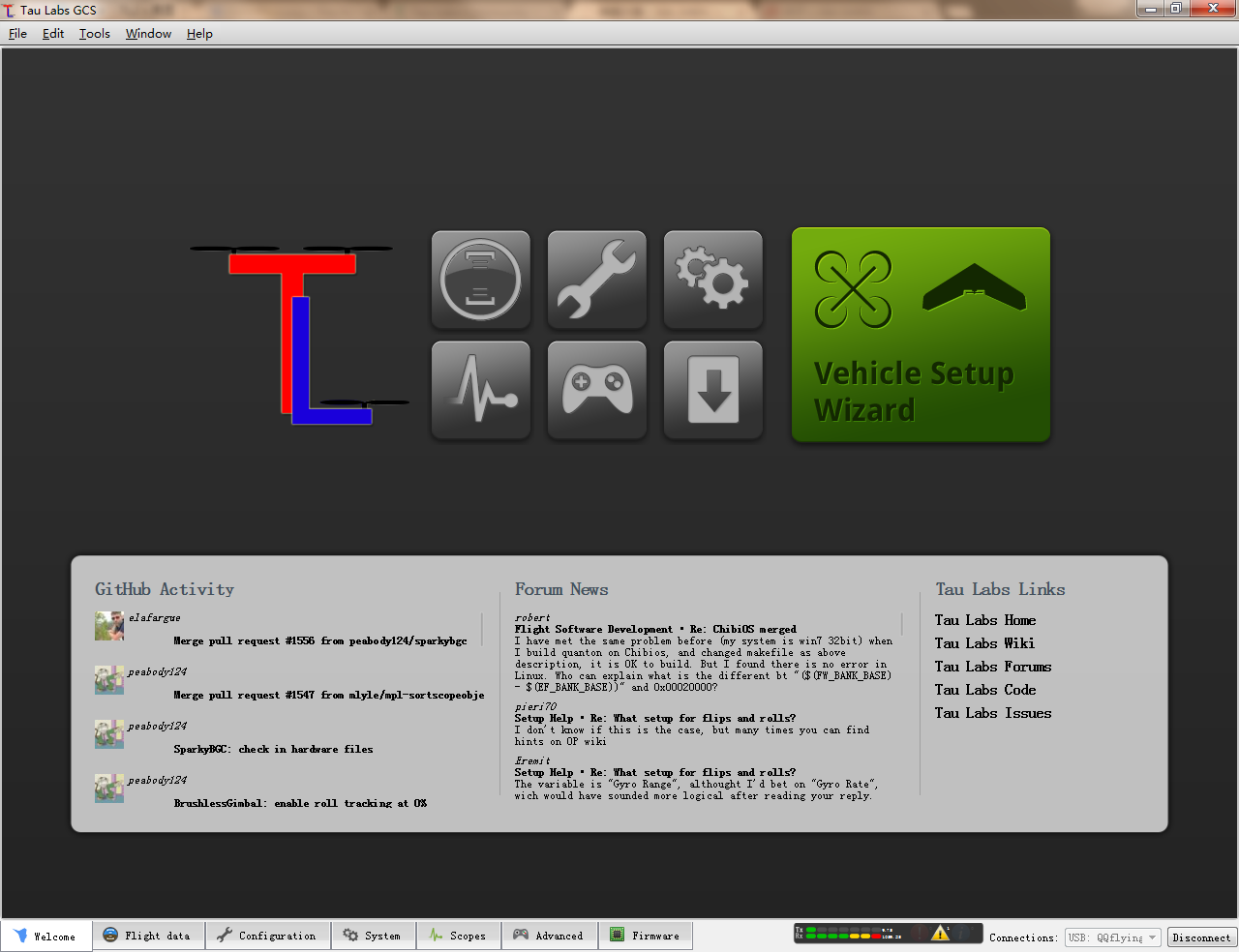
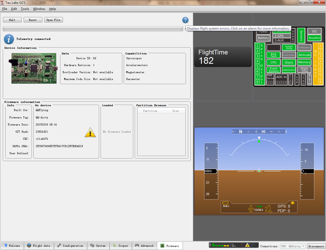
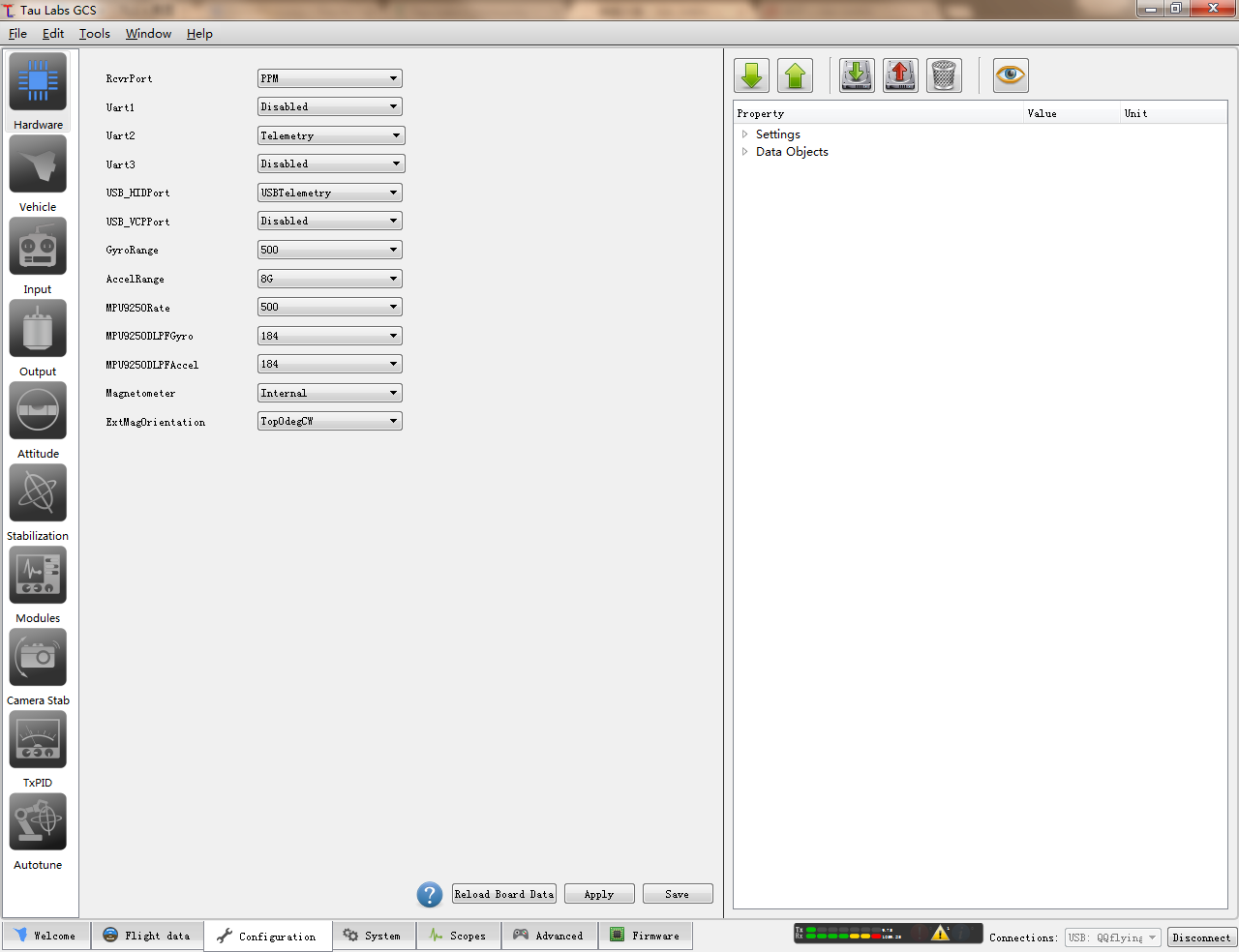
地面站的软件截图:
哈哈,下一步就是做成小板啦。PCB已经投出去了,等了
No Comments